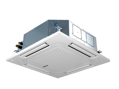
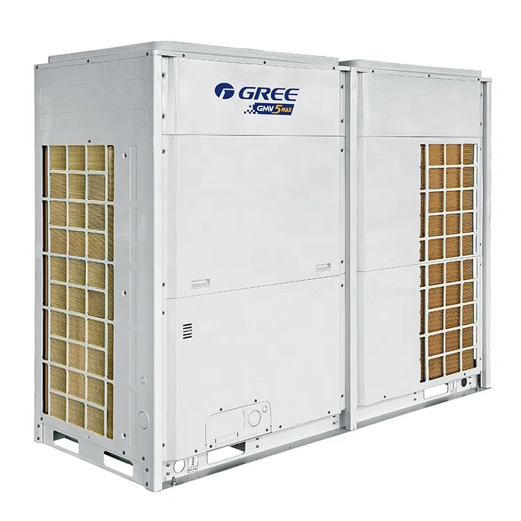
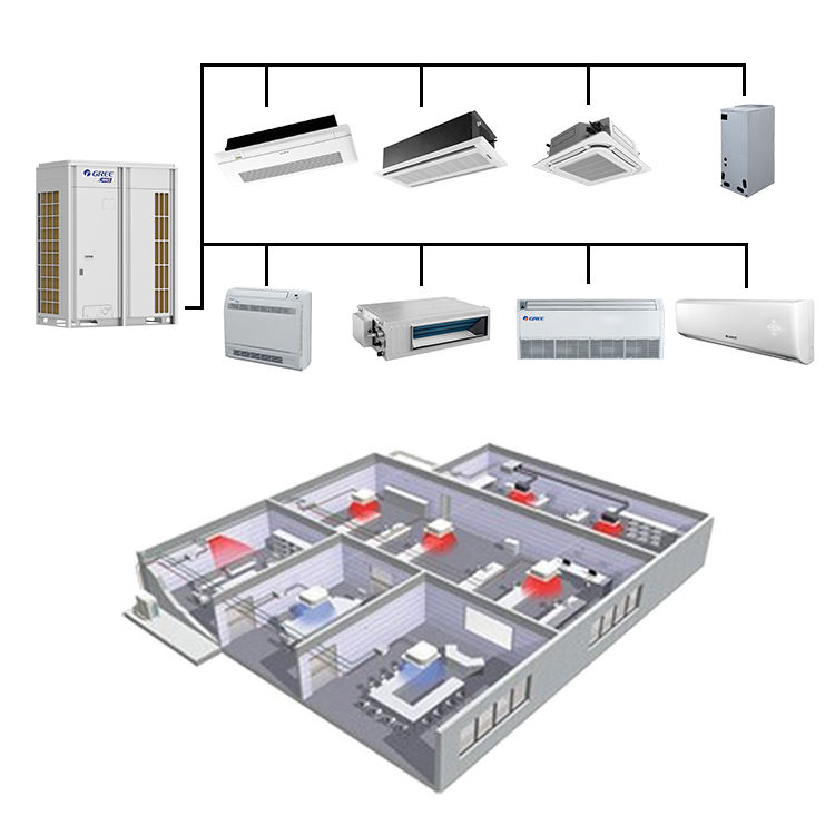
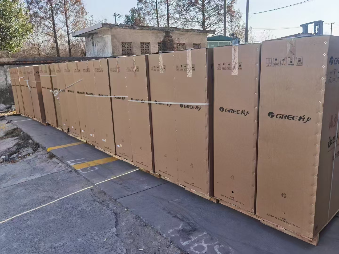
GREE 8Ton GMV DC Inverter VRF Units Outdoor Units Heat Pump
Professional Commercial Air Conditioning Solution

US$3,898 starting price
Minimum Order
1
Product Features
- My Whe Chat :+86 18551208706
- My Whats App:+86 18906202646
- BASIC OPERATING PRINCIPLE
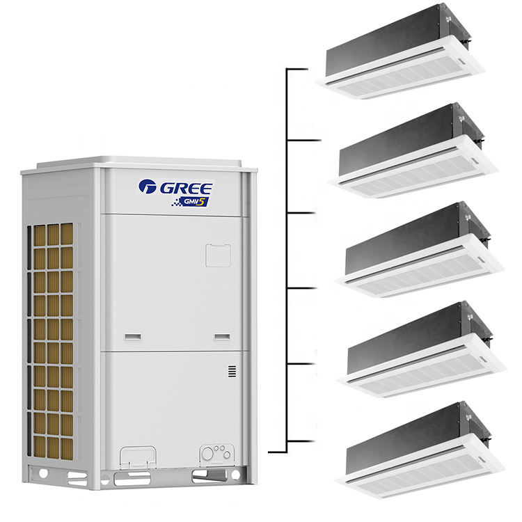
- Outdoor units of GMV5 VRF air conditioner can be implemented by combining multiple modules in
- parallel. Similarly, indoor units (IDUs) consist of multiple units connecting in parallel. The operating
- principle is as follows: When an IDU is operating in cooling mode, the outdoor unit (ODU) can
- correspondingly enable the outdoor module based on the operating load requirement of the IDU. The
- outdoor heat exchanger serves as a system condenser, and the heat exchangers of cooling IDUs are
- connected in parallel to serve as a system evaporator. The circulation of air supply and air return of the
- IDU is performed to adjust the indoor temperature and humidity. When an IDU is operating in heating
- mode, all four-way valves in the ODU module are switched into energized status. The outdoor heat
- exchange serves as the system evaporator, and the heat exchanger of the IDU serves as the system
- condenser. The circulation of air supply and air return of the IDU is performed to adjust the indoor
- temperature and humidity
- Adjusts its own rotational speed based on the actual requirement of the
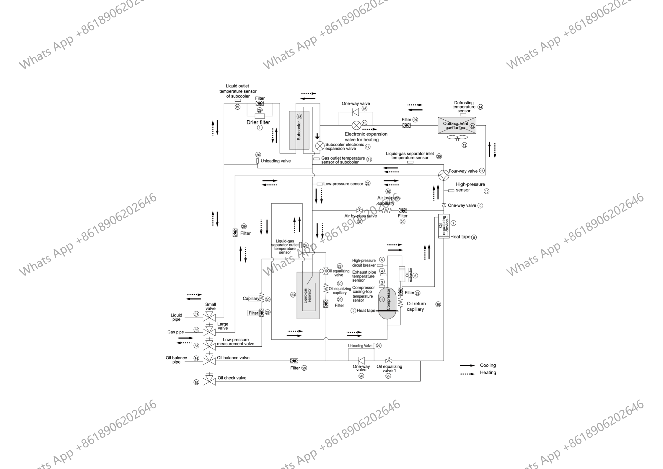
- serial number Name Main Function
- 1 、Compressor :Adjusts its own rotational speed based on the actual requirement of the system to implement capacity control.
- 2 、Compressor heat tape: Maintains a proper oil temperature in the compressor when the compressor is in standby status, ensuring the reliability during compressor startup.
- 3、Compressor casing-top temperature sensor: Detects a compressor's exhaust gas temperature for compressor control and protection.
- 4、Exhaust pipe temperature sensor of compressor:Detects a compressor's exhaust gas temperature for compressor control and protection.
- 5 High-pressure circuit breaker:Protects a compressor by sending feedback signal to stop the system when the compressor's discharge temperature exceeds the operating value of high-pressure circuit breaker
- 6 Oil extractor Separates the gas and oil in the system to ensure compressor reliability.
- 7 Oil balance device:Equalizes the oil for all modules in the case of excess oil in the current module when multiple modules are arranged in parallel, thus ensuring the system reliability.
- 8 Heat tape of oil balance device:Maintains a proper oil temperature in the compressor when the compressor is in standby status, ensuring the reliability of compressor startup.
- 9 One-way valve: Prevents high-pressure gas from entering the compressor and fast balances the suction pressure and discharge pressure in a compressor.
- 10 High-pressure sensor:Detects the high pressure value in the system in real time mode for compressor protection and other control functions.
- 11 Four-way valve: Used for the switching between the cooling and heating functions of system IDU.
- 12 Heat exchanger :Used for outdoor heat exchange.
- 13 Fan: Strengthens heat exchanging.
- 14 Defrosting temperature sensor :Used for defrosting detection.
- 15 Electronic expansion valve for heating: Controls refrigerant adjustment in heating mode.
- 16 One-way valve:Controls refrigerant flow direction.
- 17 Subcooler electronic expansion valve: Controls the degree of subcooling of tube refrigerant when the system is running in cooling mode, and reduces the capacity loss on pipes.
- 18 Subcooler: Controls the degree of subcooling of tube.
- 19 Liquid outlet temperature sensor of subcooler: Detects tube temperature.
- 20 Inlet temperature sensor of gas-liquid separator:Detects the inlet temperature of gas-liquid separator to prevent the system from running when the refrigerant flows back to the compressor.
- 21 Gas outlet temperature sensor of subcooler: Detects gas temperature of subcooler.
- 22 Low-pressure sensor :Detects system low pressure to avoid extra-low operating pressure.
- 23 Gas-liquid separator: Separate gas and liquid to prevent the system from running when the refrigerant flows back to the compressor.
- 24 Outlet temperature sensor of gas-liquid separator:Detects internal status of gas-liquid separator to further control the compressor suction performance.
- 25 Oil balance valve 1: Used for oil balance control among modules.
- 26 One-way valve :Used for oil balance control among modules and avoid reverse flow of oil.
- 27 Unloading valve :Avoids over-high pressure caused by pipeline blind spot.
- 28 Oil balance valve 2: Used for oil balance control among modules.
- 29 Filter: Prevents impurities from entering components and parts.
- 30 Capillary tube :Supports flow regulating and pressure reduction.GREE GMV5 DC Inverter VRF Units
- 31 Liquid valve :Stop valve, closed when the unit is delivered from the factory and will be opened after installation.
- 32 Gas valve: Stop valve, closed when the unit is delivered from the factory and will be opened after installation.
- 33 Low-pressure measurement valve: Detects the low pressure value or charges refrigerant during system running.
- 34 Oil balance valve :Stop valve, closed when the unit is delivered from the factory and will be opened after installation.
- 35 Oil check valve :Checks the quality of refrigerating machine oil of compressor during maintenance.
- 36 Unloading valve :Avoid over-high pressure caused by pipeline blind spot.
- 37 Air by-pass valve: Avoids extra-high or low operating pressure.
- 38 Pressure-balanced valve :Ensures success startup of compressor.
- This manual specifies safe operation requirements for GMV5 series VRF units from perspectives of
- engineering and installation, commissioning and maintenance, as well as basic principles and
- implementation methods. Professional operators must abide by relevant national (local) safety
- requirements and technical specifications set forth in this manual during operations; otherwise, the air
- conditioning system may fail or be damaged, and personnel safety accident may also occur.
Technical Specifications
Model
GMV-96WM/B -F(U)
Cooling capacity
96000Btu/h
Heating capacity
108000Btu/h
Air volume
8240CFM
Max. external static pressure
82Pa
Noise (sound level)
61dB(A)
Power
208/230V 3~ 60Hz
Input power for cooling
7.30KW
Input power for heating
7.85KW
Input current for cooling
20.37A
Input current for heating
23.5A
MOP
45A
MCA
37A
Compressor type
Inverter Scroll
Compressor quantity
1N
Refrigeration oil no. of compressor
FVC68D or FV68H
Oil Charge Compressor
1.1L
Oil Charge Oil separate tank
4L
Oil Charge Total
5.1L
Ambient temperature range for cooling
23~125.6℉
Ambient temperature range of heating
-4~75.2℉
Refrigerant type
R410A
Charging volume of refrigerant
398.7oz
Max. quantity of connected indoor unit
16unit
Size of gas pipe
Φ7/8
Size of liquid pipe
Φ3/8
Size of oil-balanced pipe
Φ3/8
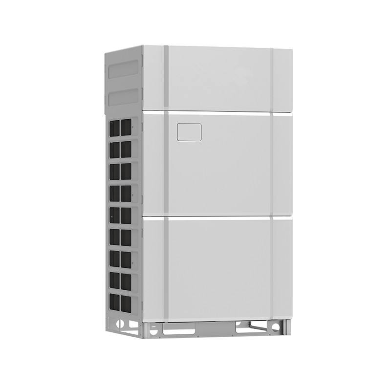
Outline dimension(WxDxH)
52-3/4x30-1/8x63-1/4
Packing size(WxDxH)
55-7/8x33-1/8x69-7/8
Net weigh
662LBS
Gross weight
695LBS


Get Professional Consultation
+86 18906202646
18906202646@189.cn
+86 18551208706
Messenger
Chat on Facebook